If your Sinoboom ground control unit is completely dead, unresponsive, or flashing communication errors, the problem is almost always a bad E-stop switch, a broken wire in the main harness, or a failure on the CAN bus network. Before you even pull out the full wiring diagram, check that both the ground and platform E-stops are pulled out.
The Quick Diagnosis
Grab your multimeter and confirm you have 24V DC at the main power connector for the ground control unit (GCU). If you've got power but no function, the problem is likely in the CAN bus wiring—those twisted green and yellow wires. A dead GCU with a good platform controller points directly to the ground/platform select switch or the GCU's dedicated power feed.
Symptoms & Identification
- No Power to GCU: The control box is completely dead, no lights, no response.
- Intermittent Power: The GCU cuts in and out when the machine is moved or vibrated.
- Communication Fault Codes: The display flashes errors related to CAN bus or communication loss.
- One Specific Function Fails: Lift works, but drive doesn't, or vice-versa from the ground controls.
- Dead Ground Controls, Live Platform Controls: This is the key symptom that isolates the fault to the ground control circuit.
Tools Required
- Multimeter (with back-probe pins)
- Deutsch pin removal tool
- Wire crimpers and strippers
- Basic socket/wrench set
Safety Warning
Disconnect the main negative battery terminal before unplugging any harnesses. Shorting a pin to ground can fry a controller instantly. Chock the wheels and use proper Lock-Out/Tag-Out procedures.
The Technical Guide: Tracing Key Circuits
1. Tracing The Main Power Supply Circuit
The ground control unit (GCU) can't function without clean power. This is always your first check when a control box is completely dead.
- Safety First: Lock out the machine and disconnect the main negative battery terminal.
- Locate the GCU Connector: Find the main multi-pin plug going into the ground control module. Your diagram will identify it, often as
X01orGCU_MAIN. - Identify Power and Ground Pins: Use the schematic to find the pin numbers for the main +24V DC input and the main ground (GND). For example, the diagram might show Pin A1 is power (Red wire) and Pin A2 is ground (Black wire).
- Reconnect Battery: Carefully and briefly reconnect the negative battery terminal for a live test.
- Test for Voltage: Set your multimeter to DC Volts. Place the red probe on Pin A1 and the black probe on Pin A2. Back-probing the connector is the best way to do this without damaging the pins.
- Good Reading: You must see 24V DC (or battery voltage, typically between 24.8V and 26.5V on a fully charged machine).
- Bad Reading (0V): If you see 0V, the problem is "upstream." The fault is in the E-stop circuit, the master switch, or the main contactor. The GCU simply isn't getting the power it needs.
- Bad Reading (<22V): Low voltage points to a poor connection, a failing battery, or a high-resistance short somewhere in the harness that's dragging the voltage down.
2. Verifying The E-Stop Safety Loop
The E-stop circuit is a simple series loop. If any E-stop button (ground or platform) is pushed, or if there's a break anywhere in that wire, the entire control system will be dead.
- Power Off: Disconnect the battery again.
- Set Multimeter to Continuity: Switch your meter to the continuity setting—the one that beeps.
- Identify E-Stop Pins: Find the pins on the GCU connector that represent the start and end of the E-stop loop. The diagram shows this as a single line running through all E-stop switches.
- Test the Loop: Place one probe on the E-stop power-in pin and the other on the E-stop power-out pin right at the GCU connector.
- Good Reading: With all E-stops pulled out, you should have continuity (the meter will beep). The circuit is complete.
- Bad Reading (No Beep): If there's no continuity, the circuit is open. Now, you hunt it down. Go to each E-stop switch one by one and test across its terminals. The one that shows no continuity when pulled out is your culprit.
3. Testing The CAN Bus Communication Lines
Communication faults usually point to an issue with the twisted pair of green and yellow wires that form the CAN bus network. The network requires a 120-ohm terminating resistor at each end; when measured together, they should read 60 ohms.
- Power Off and Battery Disconnected: This test must be done with the machine completely powered down.
- Identify CAN Pins: Locate the CAN-High (CAN-H) and CAN-Low (CAN-L) pins on a main connector. They will almost always be a twisted pair of yellow and green wires.
- Test Resistance: Set your multimeter to Ohms (Ω). Place one probe on the CAN-H pin and the other on the CAN-L pin.
- Good Reading: ~60 ohms. A reading between 58-62 ohms is perfect.
- Bad Reading (~120 ohms): This tells you that one of the two terminating resistors has failed or is disconnected from the circuit.
- Bad Reading (~0 ohms): This means you have a dead short between the CAN-H and CAN-L wires, likely from a chafed or pinched harness.
4. Tracing A Function Output Circuit (Lift Solenoid)
If just one function isn't working, the problem is likely in the output circuit running from the GCU to that function's solenoid.
- Safety and Power On: Reconnect the battery. Make sure you have a spotter.
- Identify Solenoid Pins: Find the specific pin on the GCU connector that sends power to the "boom up" solenoid valve. The schematic will label it with something like
Y10_UP. - Test for Output Voltage: Back-probe the
Y10_UPpin with your red lead, and place your black lead on a known good chassis ground. - Activate the Function: Have your spotter activate the "boom up" function from the ground controls.
- Good Reading: The multimeter should jump to 24V DC the instant the switch is activated.
- Bad Reading (0V): If the voltage stays at 0V, the GCU is not sending the signal. This could mean a bad controller, a failed input switch, or a safety interlock (like a tilt sensor) preventing the function.
- Good Reading at GCU, No Function: If you get 24V at the controller pin but the boom doesn't move, you've proven the fault is downstream. The problem is either a broken wire between the controller and the solenoid, or a burned-out solenoid coil.
How To Read A Sinoboom Wiring Diagram
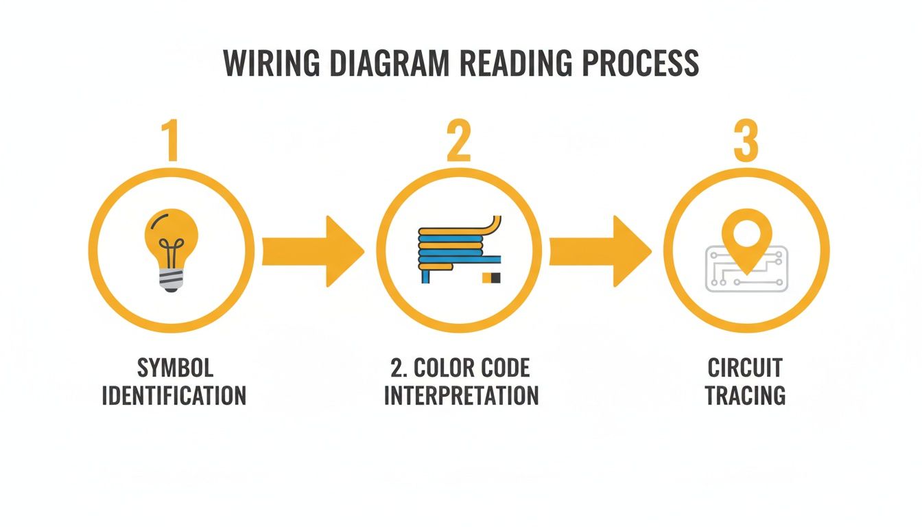
A Sinoboom wiring schematic is the machine's electrical road map. Once you learn its language, you can trace any circuit and find the exact point of failure.
Decoding The Symbols And Lines
- Switches: A broken line with a small circle or lever, labeled Normally Open (NO) or Normally Closed (NC).
- Solenoids: A coil symbol next to a valve block. When the coil gets power, it shifts a hydraulic valve.
- Sensors: Often a small box with wires, labeled by function (e.g., "Tilt Sensor").
- Contactors & Relays: A coil and a separate set of contacts. Powering the coil closes the contacts to send high-amperage current.
Every line on the diagram is a physical wire. A solid dot at an intersection means a splice or junction point.
Understanding Wire Colors And Numbers
Sinoboom uses a standardized color and number system. According to their official maintenance manuals, you'll see standardized wiring like CGND for the 12V ground. You can always confirm these details in the factory documentation, such as the complete GTJZ0608E Maintenance Manual.
| Wire Color | Primary Function | Example Circuit | | :--- | :--- | :--- | | Red (R) | Main Battery Power (Positive) | Power feed to key switch & GCU | | Black (BK) | Main Battery Ground (Negative) | GCU ground, chassis ground | | Green/Yellow (GN/YE) | CAN Bus Communication | Twisted pair between controllers | | Orange (OR) | Key Switch "Ignition" Power | Switched 24V signal to enable GCU | | White (W) | Sensor Signals | Input from tilt or pressure sensors |
Each wire is stamped with a circuit number that matches the schematic, letting you confirm you're on the right wire without tracing it through a bundled harness.
The Part You Need
Once you’ve diagnosed the failure, you need the right part to get the machine back to work. The biggest hurdle isn't the diagnosis; it's the 6- to 8-week lead time from the dealer.
- Failed E-Stop Switch: This is the most common electrical failure. When it goes, the entire safety circuit opens. Replacement is the only fix. You need a universal emergency stop switch that matches the original’s contact setup (typically one Normally Closed contact).
- Burnt-Out Solenoid Coil: If you have 24V at the solenoid connector but no function, the coil is likely burned out. Confirm with a resistance check (an open circuit means it's shot). Replace it with a coil that matches the voltage (24V DC), wattage, and inner diameter. Refer to your specific service manual for torque values—do not overtighten.
- Damaged Deutsch Connectors: Corrosion in harness connectors creates high resistance and causes intermittent faults. For light corrosion, use contact cleaner. If it's green and crusty, replace the bad pins or the entire connector body using a proper Deutsch pin tool.
Note: Components may vary by Gen 1 vs Gen 2 series. Verify with your parts manual.
China Lift Supply stocks these common Sinoboom electrical parts in the US, so you can avoid the 6-week dealer lead time and get your machine running again.
Can't wait 6 weeks for this part? We have it on the shelf in Kansas. Check the price and availability here: https://www.chinaliftsupply.com.