
If your Sinoboom is dead at startup and flashing Error Code 02, the ECU and the platform PCU aren't talking. Over 90% of the time, this fault is caused by a bad connection, a damaged CAN bus harness, or a blown terminating resistor, not a fried controller.
The Quick Diagnosis
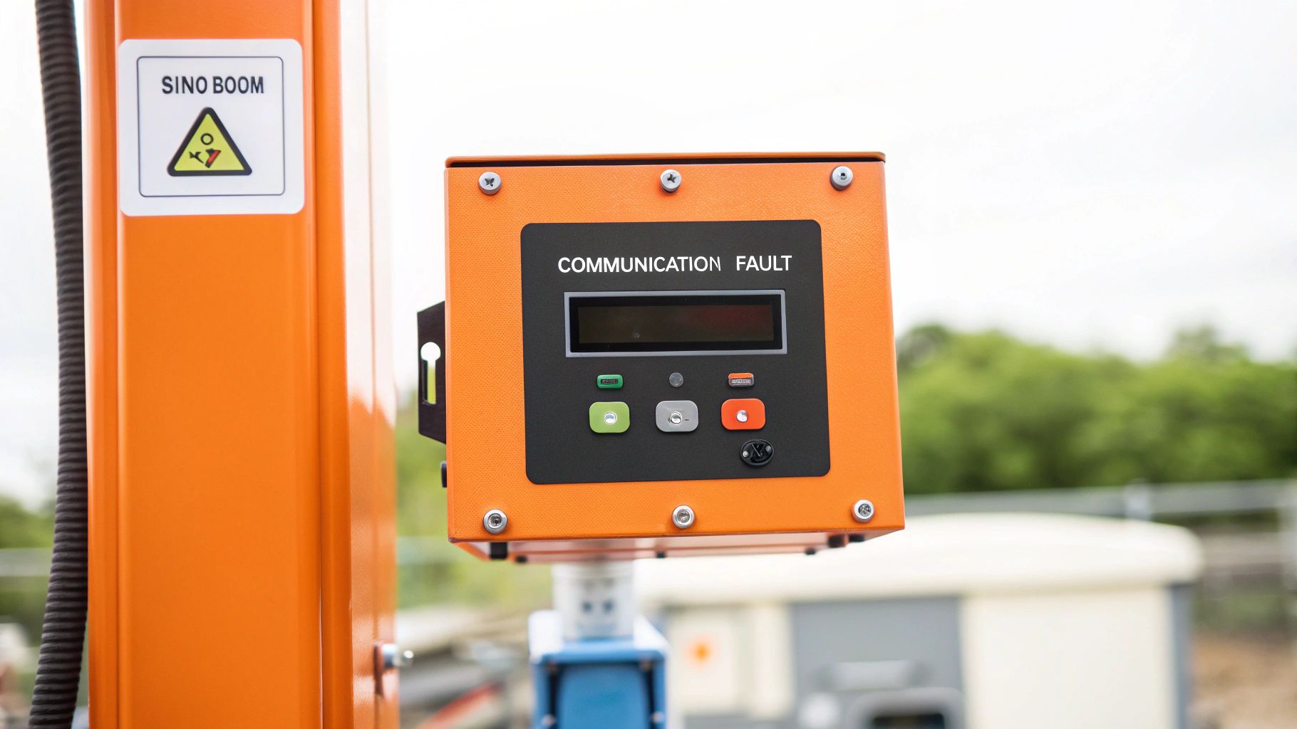
Error Code 02 is a System Communication Fault. It means the communication link between the ground controller and the platform controller is broken. The most likely culprit is physical damage to the main harness in the scissor stack or water inside an electrical connector.
Symptoms & Identification
You're in the right place if your machine shows this exact combination of symptoms:
- Total Lockout: The machine is unresponsive from the moment you turn the key at either the ground or platform controls.
- Code 02 on Display: The LCD screen at the ground controls immediately flashes "Error Code 02" or a message about system initialization/communication failure.
- Continuous Alarm: A steady, non-stop alarm sounds as soon as the code appears and won't stop until the machine is powered down.
Tools Required
- Digital Multimeter: Must have a reliable Ohms (Ω) setting.
- Metric Socket & Wrench Set: Primarily 10mm and 13mm.
- Electrical Contact Cleaner: Residue-free is non-negotiable.
- Small Pick Set: For inspecting female connector pins.
- Dielectric Grease: To prevent future moisture intrusion.
Safety Warning
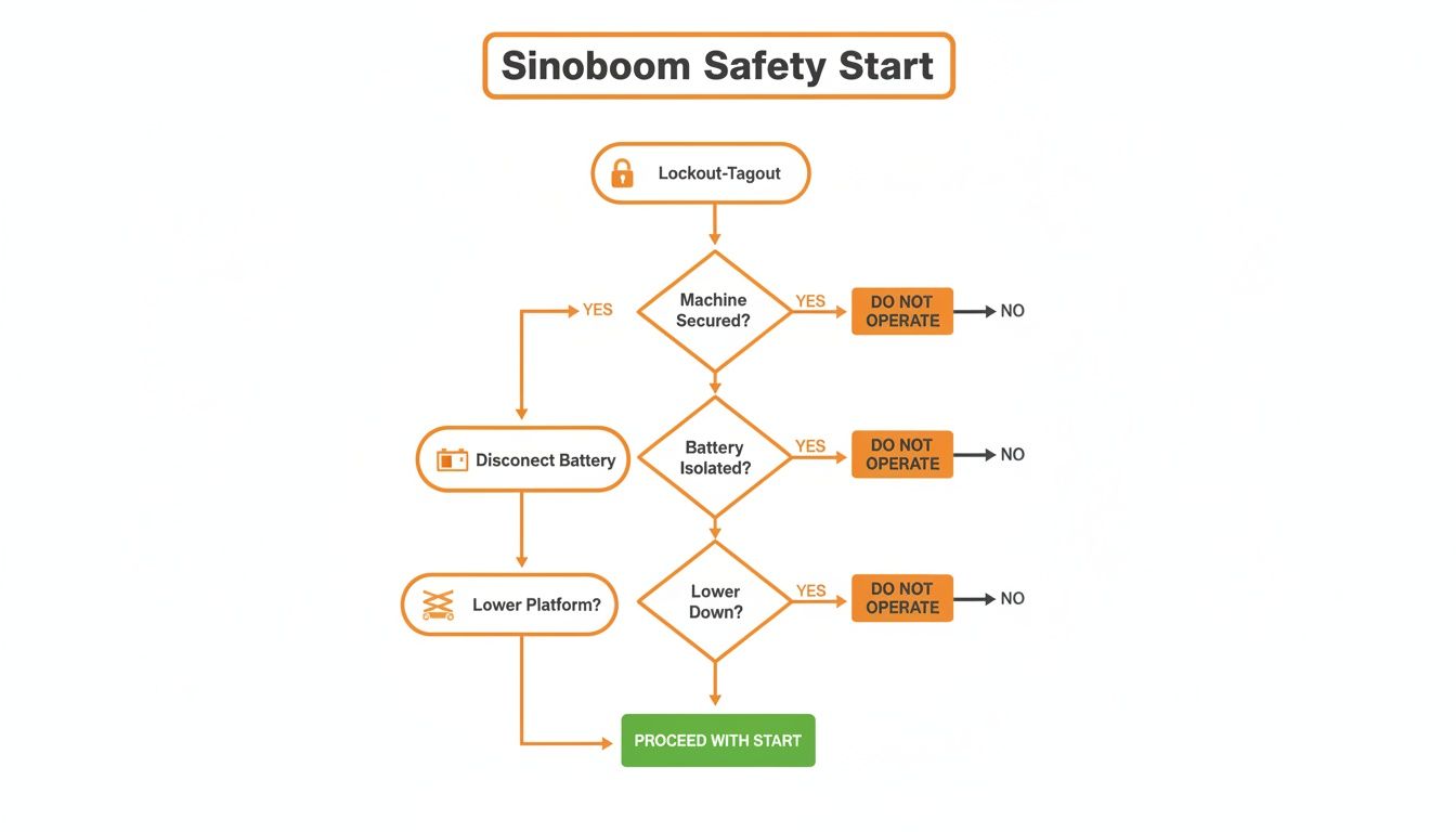
Isolate all power before starting work. A complete lockout-tagout procedure is mandatory. Physically disconnect the negative battery terminal. An accidental arc from a slipped wrench can instantly smoke the ECU. If the platform is raised, lower it using the emergency descent valve and chock the wheels securely.
The Technical Guide (Step-by-Step)
This is a logical diagnostic process. Don't skip steps.
-
Perform a full power cycle. Turn the key off, wait a solid 30 seconds for all capacitors to discharge, then power it back on. If the code returns, proceed to the next step.
-
Conduct a visual inspection. Your eyes are the best first tool.
- Check the main harness running up the scissor stack. Look for pinch points where the arms pivot, abrasions where it rubs against the frame, or signs of stretching. This is the most common failure point.
- Inspect connectors at both the ground control box and the platform control box. Look for obvious corrosion (white or green powder), pushed-back pins, or signs of water intrusion.
- Mechanic's Tip: The two most vulnerable spots for the CAN bus harness are the main pivot point of the scissor stack and the entry point into the platform control box. Start there.
-
Test the CAN Bus resistance. If the visual check shows nothing, grab your multimeter.
- Ensure the machine is OFF and the negative battery cable is DISCONNECTED.
- Locate the CAN bus wires in the main harness connector at the ground controller. They are typically a twisted pair: yellow (CAN High) and green (CAN Low).
- Set your multimeter to Ohms (Ω). Place one probe on the CAN High pin and the other on the CAN Low pin.
- A healthy circuit must read between 58 and 62 Ohms. This confirms the two 120 Ohm terminating resistors (one in each controller) are connected and the circuit is intact.
-
Interpret the Ohm reading.
- Reading is 120 Ohms: One terminating resistor is missing from the circuit. This means there's a break in the CAN High or CAN Low wire, or a bad connection at one of the controllers.
- Reading is 0 Ohms: You have a dead short between the CAN High and CAN Low wires, likely from a pinched harness.
- Reading is "OL" (Open Line): There's a complete break in one or both of the CAN wires.
-
Isolate the fault.
- Disconnect the main harness at the platform control box.
- Repeat the Ohm test at the ground controller's harness connector. It should now read 120 Ohms. If it does, the ground controller is good.
- This test proves the fault is in the main harness running up the scissor stack or in the platform controller. You can now use your meter's continuity function to test each wire in the harness end-to-end to find the exact break.
- Note: Components may vary by Gen 1 vs Gen 2 series. Verify with your parts manual.
The Part You Need
Once you’ve found a break in the main communication cable, the only correct repair is to replace the entire harness. Field splices on CAN bus wires are temporary at best and will fail again from the constant flexing of the scissor stack. A bad splice will cause intermittent communication errors that are a nightmare to track down later.
Don't let downtime kill your project while you wait 6-8 weeks for a harness from the dealer. China Lift Supply stocks OEM-compatible Sinoboom CAN bus harnesses in the US to avoid the 6-week dealer lead time. These are built to the correct spec with proper shielding to ensure a reliable, long-term repair.
Final Verification and System Checkout
- Reconnect the battery and power on the machine. Verify that Error Code 02 does not reappear.
- Perform a full function test from both the platform and ground controls. Cycle lift, drive, and steer functions completely.
- Clear the fault code history from the machine's diagnostic menu. If you don't, the next mechanic will be chasing old codes.
- Log the repair in your maintenance records, noting the code, the fix, and the machine hours.
Can't wait 6 weeks for this part? We have it on the shelf in Kansas. Check the price and availability here: https://www.chinaliftsupply.com.