If your LGMG AS1413 is flashing a fault code, it's usually pointing to one of two areas: battery voltage (Codes 2, 3, 23) or sensor communication (Codes 34, 41). These issues often boil down to a bad battery connection or a nicked wire in a harness. This guide gives you the full code list and the steps to get it fixed fast.
The Quick Diagnosis
For voltage codes (02, 03, 23), the problem is almost always a corroded terminal, a weak battery, or the wrong charger. For sensor codes (34, 41, 44), check the sensor's physical condition and wiring first. Most LGMG faults are caused by simple electrical or physical issues, not a failed ECU.
Symptoms & Identification
Before you look up a code, what the operator sees is your first clue. This confirms you're on the right track.
- No Power: Machine is a brick. Blank display, no response from controls.
- Lift Only, No Drive: Platform functions work, but the machine won't move.
- Drive Only, No Lift: Machine drives, but platform functions are dead.
- Jerky Operation: Lift or drive functions stutter or feel intermittent.
- Constant Alarm: A piercing alarm won't shut off, often with a flashing beacon.
- Charging Failure: The onboard charger shows an error light and won't charge.
Tools Required
- Multimeter (with sharp probes)
- Insulated metric wrench and socket set
- Battery terminal brush
- Dielectric grease
- Hydraulic pressure gauges
- Laptop with LGMG diagnostic software (for deep communication faults)
Safety Warning
The battery and motor controller circuits carry high voltage. Always disconnect the main battery negative terminal first before starting any electrical work. If working under the platform, always engage the manufacturer-approved safety prop.
The Technical Guide (Step-by-Step)
This is the full reference for every fault code your LGMG AS1413 can throw. It's organized by system: Power, Drive, Lift, and Controller faults. Find your code and follow the steps.
First, your mandatory safety check.
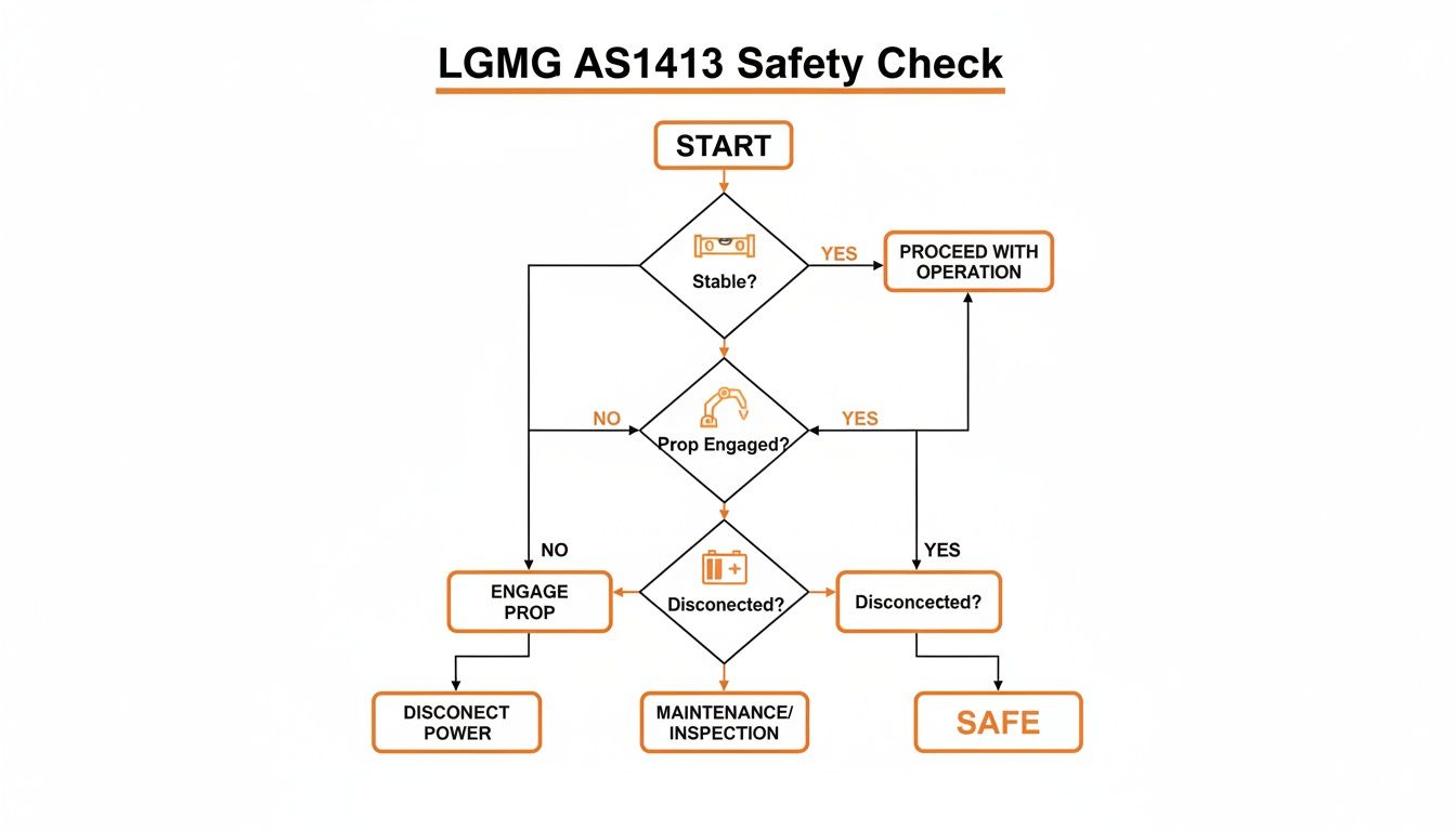
This flowchart isn't a suggestion; it’s the mandatory check to ensure the machine is stable, the safety prop is in, and power is cut before you start.
Power and Battery System Faults
Nine times out of ten, a power-related code is something simple with the batteries or charger, not a major system failure.
Code 02 Battery Voltage Too Low
- What the ECU Sees: System voltage has dropped below its minimum, usually around 21V. This is a safety lockout to protect electrical components.
- Symptoms: Machine won't power on, or it flickers on and immediately faults. No functions will work.
- Diagnosis & Fix:
- Check Battery State of Charge: Put your multimeter across the main battery terminals. A healthy, fully charged pack should read >25.2V. If low, perform a full charge cycle.
- Inspect Terminals: Look for white or green corrosion. Disconnect, clean with a terminal brush, and reconnect. Refer to your specific service manual for torque values—do not overtighten.
- Load Test Batteries: If voltage seems okay but dies under load, you have a bad cell. Perform an individual load test on each battery to find the weak link.
Code 03 Battery Voltage Too High
- What the ECU Sees: Voltage spike over the safe limit, typically above 32V. Almost always caused by the wrong charger or a faulty voltage regulator in the correct one.
- Symptoms: Machine faults out during or right after charging. The charger itself may show a fault light.
- Diagnosis & Fix:
- Verify Charger: Ensure you're using the correct OEM charger for the AS1413's 24V system.
- Test Charger Output: Disconnect the charger from the machine and test its output voltage. If it’s significantly higher than its rating, the charger is bad and must be replaced.
Code 23 Charger Communication Fault
- What the ECU Sees: The ECU is not receiving the expected "handshake" signal from the onboard charger via the CAN-Bus.
- Symptoms: Machine may not power on or will power on but refuse to charge. Charger indicator lights may flash an error pattern.
- Diagnosis & Fix:
- Inspect Charger Connection: Ensure the main plug is fully seated and the pins are clean and straight.
- Trace Data Wire: Inspect the small data wire within the charging cable for pinches, cuts, or breaks.
- Check ECU Connector: Pull the main ECU connector and verify the pin for the charger communication wire is secure and not pushed back.
Drive System Faults
These codes relate to the drive motors and brakes. The machine will lock out all drive functions as a safety precaution.
Code 11 Left Drive Motor Fault
- What the ECU Sees: An open circuit, short to ground, or excessive current draw in the left drive motor circuit.
- Symptoms: The left wheel will not drive. The machine will attempt to pivot around the dead wheel.
- Diagnosis & Fix:
- Check Motor Connections: Ensure the heavy-gauge cables at the left drive motor are tight and free of corrosion.
- "Ohm Out" the Motor: Disconnect the motor and use a multimeter to check resistance between the motor posts. An open loop (infinite resistance) or a short to the motor case indicates internal failure.
- Inspect Motor Brushes: On brushed DC motors, check for worn or stuck brushes.
Code 12 Right Drive Motor Fault
- What the ECU Sees: Same as Code 11, but for the right motor circuit.
- Symptoms: The right wheel will not drive.
- Diagnosis & Fix: Follow the exact same steps as for Code 11, but focus on the right drive motor and its wiring.
Code 16 Brake Release Fault
- What the ECU Sees: The controller is not receiving the expected electrical feedback when it commands the brakes to release.
- Symptoms: The lift will not move. You may hear a "click" from the controller, but the brakes remain engaged.
- Diagnosis & Fix:
- Check Brake Wiring: Inspect wires going to both drive motor brakes for damage.
- Test Brake Coils: Unplug the brake wires and measure the resistance of each coil. Refer to the service manual for the correct range. An open or shorted coil requires a new brake assembly.
- Verify Voltage at Brakes: (Live Test - Use Caution) Check for 24V at the brake connector when drive is commanded. No voltage points to a problem upstream in the harness or controller.
Lift System Faults
This group covers the lift pump motor, hydraulic solenoids, and pothole guard system.
Code 15 Main Contactor Fault
- What the ECU Sees: The main power contactor is either stuck open (not closing) or welded shut (not opening).
- Symptoms: No hydraulic functions (lift/lower) will work. The pump motor will not run.
- Diagnosis & Fix:
- Listen for the "Click": Have an operator attempt to lift while you listen near the contactor for a solid "click." No sound points to a coil issue.
- Check Coil Voltage: Check for 24V at the small coil terminals when a function is commanded. Voltage with no click means a bad contactor.
- Check Main Posts: If it clicks but the pump doesn't run, check for voltage across the large posts. When closed, you should see battery pack voltage on both sides. If not, the internal contacts are fried.
Code 21 Lift Solenoid Fault
- What the ECU Sees: An open or shorted circuit in the coil for the main lift solenoid valve.
- Symptoms: The machine will not lift. Other functions like drive and lowering may work.
- Diagnosis & Fix:
- Inspect Solenoid Wiring: Check the plug and wires at the lift solenoid for a clean, tight connection.
- Test Coil Resistance: Unplug the solenoid and measure its coil resistance. An open circuit (no reading) or a dead short means the coil has failed.
- Verify Voltage: Check for 24V at the solenoid connector when the lift button is pushed. No voltage indicates an issue in the harness or controller.
Code 44 Pothole Guard Limit Switch Fault
- What the ECU Sees: A conflicting signal from one of the pothole guard limit switches.
- Symptoms: The machine drives but will only lift a few feet before stopping.
- Diagnosis & Fix:
- Visual Inspection: Lower the machine fully and inspect both pothole guard mechanisms for rocks, mud, or bent arms.
- Clean and Lubricate: Clean the mechanisms and work them by hand to ensure they move freely.
- Test Switches: Use a multimeter to test the continuity of each limit switch. It should change state (open/closed) as the pothole guard deploys.
Controller and Communication Faults
These can be tricky, often pointing to sensors, joysticks, or the main ECU.
Code 34 Tilt Sensor Alarm
- What the ECU Sees: The chassis is on a slope greater than the safe limit (usually 2-3 degrees).
- Symptoms: All lift and drive functions are disabled. A loud, non-stop alarm will sound.
- Diagnosis & Fix:
- Move to Level Ground: This is the fix 99% of the time.
- Check Sensor Mounting: Ensure the tilt sensor is securely bolted to the chassis.
- Test Sensor Output: If the machine is on level ground and still alarming, test the voltage output from the sensor. An incorrect or missing signal points to a failed sensor.
Code 41 Platform Overload
- What the ECU Sees: The pressure sensor in the lift cylinder line is reading a pressure that translates to too much weight in the platform.
- Symptoms: The platform will not lift, though lowering is usually possible. Drive is often disabled.
- Diagnosis & Fix:
- Remove Weight: Ensure the platform is not actually overloaded.
- Inspect Sensor Wiring: Check the wires running to the pressure transducer, usually near the base of the lift cylinder.
- Calibrate System: If the fault persists with an empty platform, the system may need recalibration with a diagnostic tool. If it won't calibrate, the sensor is likely bad.
Code 55 Controller Internal Fault
- What the ECU Sees: The ECU has failed its internal self-check. This is a critical failure.
- Symptoms: The machine is dead or acting completely erratically. This code is a hard stop.
- Diagnosis & Fix:
- Power Cycle: Disconnect the main negative battery terminal, wait a full 60 seconds, then reconnect. This can sometimes clear a software glitch.
- Check All Connections: Meticulously check every connector at the ECU for cleanliness and a secure fit. A bad ground can sometimes mimic this fault.
- Replace ECU: If the code returns immediately after a power cycle and all connections are perfect, the controller has failed and must be replaced.
Note: Components may vary by Gen 1 vs Gen 2 series. Verify with your parts manual.
The Part You Need
You've figured out the problem. Now, the real enemy is downtime. The most common replacement parts for these faults are battery chargers, tilt sensors, contactors, and solenoids. Waiting 6-8 weeks for a part from the dealer isn't an option.
China Lift Supply stocks these specific OEM-compatible parts in the US to avoid that dealer lead time. A replacement charger or sensor isn’t weeks away; it's on a truck the same day you order it. This is how you get your machine back to work without the agonizing wait.
Frequently Asked Questions
How do I clear fault codes on an LGMG AS1413?
Most codes clear themselves once the underlying issue is fixed. For stubborn codes, perform a full power cycle: shut down the machine, disconnect the main negative battery terminal for 60 seconds, and reconnect. If the code persists, the root problem is still present.
Can I use a universal controller on my AS1413?
No. The AS1413's controller has specific CAN-Bus protocol compatibility requirements to communicate with all other components. A non-verified controller will cause a cascade of communication faults. Stick with an OEM-compatible part verified for this model.
What's the difference between a solid and beeping alarm?
- Solid, continuous alarm: Critical, machine-disabling fault (e.g., Code 34 Tilt Alarm). STOP immediately.
- Intermittent beeping alarm: A warning for a less severe or intermittent issue, like a sensor on the edge of its limit or a loose wire.